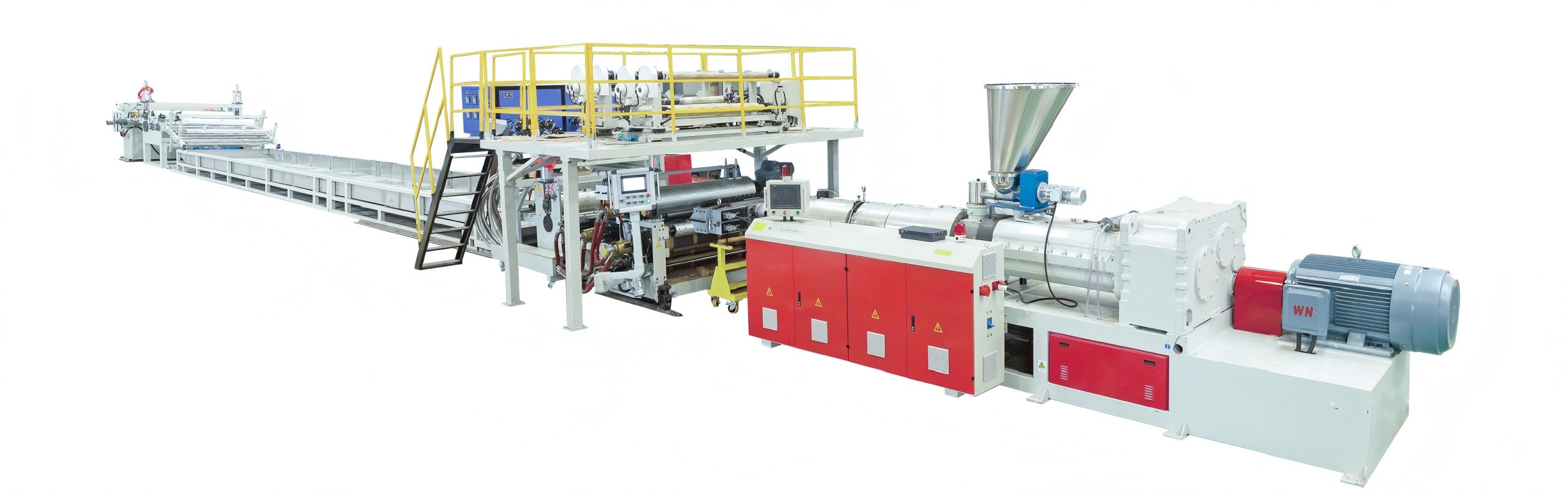
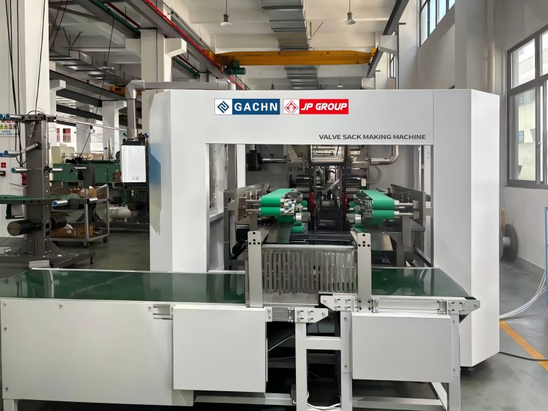
In the PP woven valve bag production field, the bag making machine, as the core terminal equipment, directly determines the product qualification rate, production efficiency, and overall cost. Xiamen Gachn Group, with over ten years of experience in the industry, has independently developed the FK008-Ⅲ valve bag making machine, which, thanks to its patented technology, intelligent configuration, and stable performance, has become the choice of over 50 projects worldwide. Today, we've compiled the 10 most frequently asked questions from customers, providing a comprehensive breakdown of the core advantages and key usage points of this equipment, from technical parameters to practical applications.
I. Core Configuration and Performance: These Key Parameters Directly Affect Production Efficiency
Q1: What specifications of valve bags can the FK008-Ⅲ produce? What are its applicable scenarios?
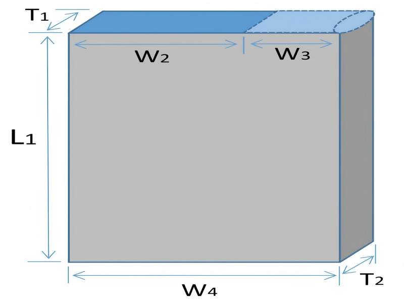
A: This equipment primarily produces PP woven single-layer coated valve bags, covering capacity requirements from 10-50kg. Specific specifications are as follows: bag width (W1) 300-620mm, inner valve width (W3) 80-200mm, outer valve width (W4) 130-300mm, bag length (L1) 360-750mm, fully meeting the packaging needs of industries such as chemical, cement, grain, and building materials. It is currently operating stably in overseas markets such as Uzbekistan and Saudi Arabia, as well as in large-scale projects in Jiangxi, Guizhou, and Fujian provinces in China, adapting to the raw material characteristics and production standards of different regions.
Q2: How is the equipment's production efficiency and stability? Is it capable of continuous operation?
A: The FK008-Ⅲ achieves a stable production speed of 110-120pcs/min. Equipped with a full servo control system and internationally renowned brand components (Schneider PLC, NSK bearings, etc.), the dynamic error is less than 0.01mm, ensuring smooth sealing and precise dimensions even at high speeds. The equipment supports operation in a wide temperature range of -20℃ to 60℃. Its dust-resistant and voltage fluctuation-resistant design results in a failure rate of less than 0.5%, enabling 30 days of continuous, downtime-free production, making it particularly suitable for large-scale mass production.
Q3: Compared to ordinary bag-making machines, what are its advantages in cost control?
A: The core advantages are concentrated in two aspects: raw material savings and energy consumption optimization:
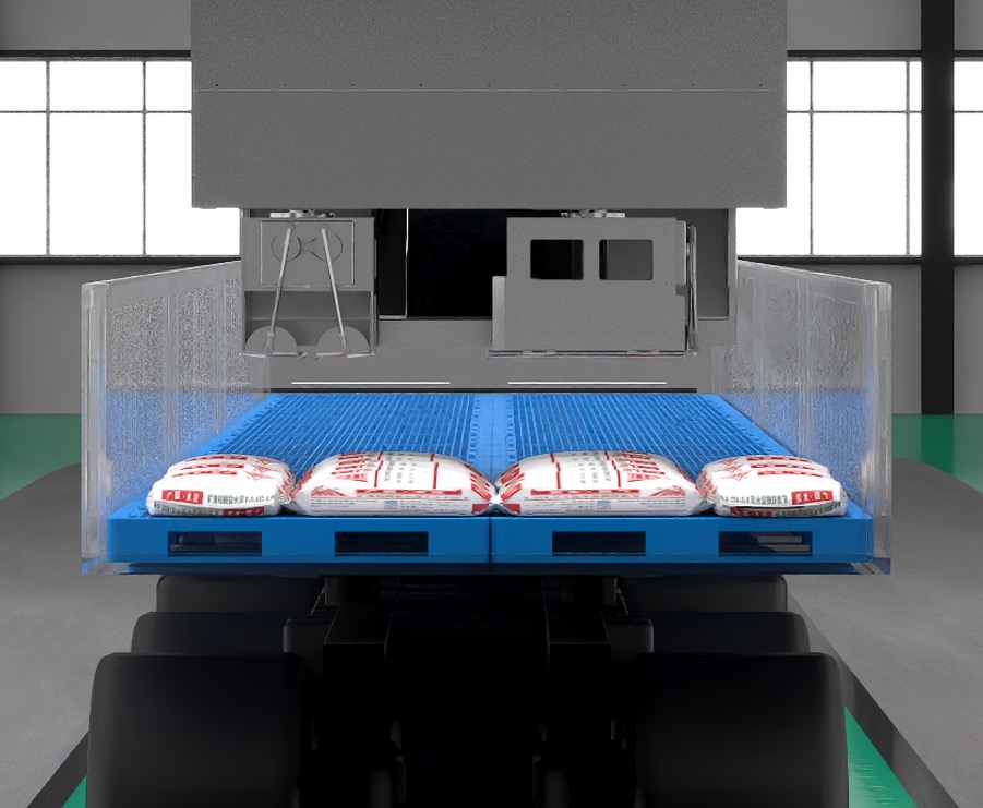
1. Patented bottom sealing technology: Utilizing single-sided film material and a narrow bottom overlap design, it saves $1 in raw material costs for every 500 bags produced. A production line with an annual capacity of 30 million bags can save $60,000 annually.
2. Intelligent energy-saving system: Vector frequency conversion technology reduces motor energy consumption by 10%-30%, automatically entering sleep mode during standby and intelligently boosting voltage under high load, saving tens of thousands of yuan in electricity costs annually.
3. AI visual inspection replaces manual labor: One operator can manage 3-4 machines simultaneously, reducing labor costs by 240,000-360,000 yuan per production line annually.
II. Technological Innovation and Patents: These Cutting-Edge Technologies Solve Industry Pain Points
Q4: What is the patented triangular bag opening technology? How is it superior to traditional designs?
A: This is Gachn's core innovation. It achieves bag opening formation through vacuum negative pressure, eliminating the need for easily damaged parts such as suction cups. Traditional bag-making machines' suction cups frequently contact materials, leading to wear, leakage, unstable bag opening formation, and high maintenance costs. The FK008-Ⅲ's contactless design not only offers faster forming speed and stronger stability but also reduces the replacement of easily damaged parts by 90%, lowering subsequent maintenance workload and costs.

Q5: What defects can the AI vision inspection system identify? What is its accuracy rate?
A: The system fully covers two major categories of problems: base fabric defects and bag-making defects. These include round threads, holes, coarse threads, joints, and scratches in the base fabric, as well as bottom sticker misalignment, sticker folding, missing corners, and incomplete sealing during the bag-making process. AI adaptively identifies defects without manual marking, achieving a false negative rate as low as 0.05%. Compared to manual inspection, the accuracy is improved by more than 3 times, and defect data can be tracked in real time, providing a basis for production process optimization.
Q6: Is the equipment highly automated? Does it require high skill levels from operators?
A: The equipment uses a user-friendly human-machine interface with a fully Chinese/English control panel. Parameter settings, fault warnings, production counting, and other functions are clearly displayed. Ordinary workers can operate it independently after 1-2 days of training, and the maintenance team only needs 2 mechanical engineers and 1 electrical engineer per shift. We also provide detailed Chinese and English operation manuals and video tutorials, and on-site training combines hands-on practice to ensure immediate usability upon production.
III. Installation, Commissioning, and After-Sales Service: Is the overseas project implementation guaranteed?
Q7: What are the installation and commissioning procedures after overseas customers purchase the equipment?
A: Gachn provides turnkey service with complete transparency throughout the process:
1. 100% full-machine testing is completed before equipment leaves the factory to ensure compliance with export standards;
2. Standard ocean-going packaging is used for sea freight, with a professional customs clearance team assisting with procedures;
3. Upon arrival at the site, 8 professional technicians provide on-site service, completing installation, commissioning, and trial production within 30 days;
4. During the trial production phase, parameters will be optimized based on actual output until the product qualification rate reaches the agreed standard before acceptance.
Q8: What does the training include? How is after-sales technical support guaranteed?
A: Training adopts a combined "theory + practice" model, covering equipment structure principles, daily operation, parameter adjustment, common troubleshooting, maintenance, etc., and customized training materials are also provided. Regarding after-sales support, the equipment enjoys a 12-month full-machine warranty (including electrical and mechanical systems), and free upgrades to the electrical control system within 3 years; whether domestic or overseas, the after-sales team will respond to fault inquiries within 24 hours, and in emergencies, technicians can be coordinated for on-site service.
Q9: What are the requirements for the factory and supporting facilities for the equipment?
A: The space required for a single unit is 12m long × 7.5m wide × 2.5m high. It is recommended that the entire production line factory be no less than 85m × 60m (including equipment placement and material handling area). Supporting facilities must meet the following requirements: 380V three-phase five-wire power supply (total power 150KW, operating power 60KW), 0.6m³/h cooling water flow, and 6-7 bar compressed air (3m³/min). These are standard configurations for conventional industrial production; customers can prepare them in advance according to their own circumstances.
IV. Practical Application and Expansion: These Details Help You Avoid Production Risks
Q10: Does the equipment have special requirements for raw materials? Is it compatible with PP raw materials from different regions?
A: Raw materials must meet the following standards: PP drawing grade raw materials (MFI 3.5-5.0g/10min, 230℃), coating grade raw materials (PP coating grade MFI 18-40g/10min, or 85% PP + 15% LDPE mixed raw materials). Additives can include conventional auxiliaries such as calcium carbonate masterbatch. Our equipment is adapted to the characteristics of raw materials in different regions worldwide. In the early stages of a project, we will conduct targeted adjustments based on the raw material samples provided by the customer to ensure stable production of qualified products even with slight fluctuations in raw material indicators.
Further Consideration: Why are more and more overseas customers choosing Gachn's bag-making machines?
Besides the technological advantages of the equipment itself, comprehensive full-industry chain support is key: Gachn can provide complete line solutions from drawing, circular weaving, coating, printing to bag making, avoiding compatibility issues between different brands of equipment; 200+ national patents (including 28 invention patents) ensure no technology infringement risks; extensive overseas project experience and familiarity with customs policies, industrial standards, and service requirements in different regions make project implementation smoother.
If your company is planning a valve bag production line or wants to upgrade your existing bag making equipment, feel free to contact us for a customized solution! Fill out the consultation form below, and our technical consultants will provide you with equipment selection advice, capacity calculations, and detailed quotations within 48 hours. You can also get a free FK008-Ⅲ equipment operation video and a success story manual.