dyyseo
Thermal Shock Testing

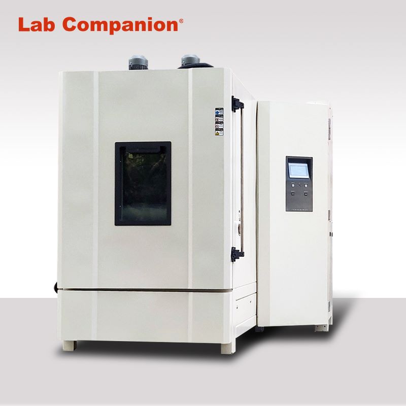
Technical Characteristics and Engineering Applications of Rapid Temperature Change Test Chambers

This article analyzes the system architecture and technical characteristics of rapid temperature change test chambers, by systematically studying the technical parameters and functional design of key components, it provides theoretical guidance for equipment selection and process optimization.


1.Technical Principles and System Architecture

Rapid temperature change test chambers operate based on thermodynamic transfer principles, achieving nonlinear temperature gradient variations through high-precision temperature control systems. Typical equipment can attain temperature change rates ≥15℃/min within a range of -70℃ to +150℃. The system comprises four core modules:

(1) Heat exchange system: Multi-stage cascade refrigeration structure

(2) Air circulation system: Adjustable vertical/horizontal airflow guidance

(3) Intelligent control system: Multivariable PID algorithm

(4) Safety protection system: Triple interlock protection mechanism


2.Analysis of Key Technical Features

2.1 Structural Design Optimization

The chamber adopts modular design with SUS304 stainless steel welding technology. A double-layer Low-E glass observation window achieves >98% thermal resistance. The CFD-optimized drainage channel design reduces steam condensation to <0.5 mL/h.


2.2 Intelligent Control System

Equipped with Japan-made YUDEN UMC1200 controller.


2.3 Refrigeration System Innovation

Incorporates French Tecumseh hermetic scroll compressors with R404A/R23 refrigerants.

 3.Safety and Reliability Design

3.1 Electrical Safety System


  • Complies with IEC 61010-1 CLASS 3
  •  
  • Schneider Electric components with full-circuit isolation
  •  
  • Grounding resistance <0.1Ω
  •  
  • Overcurrent protection response <0.1s


3.2 Multi-level Protection

  • Triple-channel PT100 temperature monitoring
  • Dual pressure switches
  • Dry-burn humidity protection
  • Emergency pressure relief valve


4.Technological Applications

(1) Aerospace: Thermal-vacuum testing for satellite components

(2) New energy vehicles: Battery pack thermal shock tests

(3) Microelectronics: Chip package reliability verification

(4) Materials science: Composite interlayer thermal stress analysis


5.Technological Trends

(1) Multi-stress coupling tests: Temperature-vibration-humidity simulation

(2) Digital twin integration: Virtual system modeling

(3) AI-driven parameter optimization: Machine learning-based curve tuning

(4) Energy efficiency: 40%+ heat recovery rate


Conclusion: With increasing reliability requirements in advanced industries, future development will emphasize intelligent operation, high precision, and multidimensional environmental simulation. Subsequent research should focus on integrating equipment with product failure mechanism models to advance environmental testing from verification to predictive analysis.

Click to view related products.

Lab Companion, your trusted brand.
阅读全文......

Specification of Temperature Cycle and Temperature Shock Test

Instructions:

Early temperature cycle tests only look at the air temperature of the test furnace. At present, according to the requirements of relevant international norms, the temperature variability of the temperature cycle test refers not to the air temperature but the surface temperature of the product to be tested (such as the air temperature variability of the test furnace is 15°C/min, but the actual temperature variability measured on the surface of the product to be tested may only be 10~11°C/min), and the temperature variability that will rise and cool down also needs symmetry, repeatability (the rise and cooling waveform of each cycle is the same), and linear (the temperature change and cooling speed of different loads is the same). In addition, lead-free solder joints and part life assessment in advanced semiconductor manufacturing processes also have many requirements for temperature cycle testing and temperature shock, so its importance can be seen (such as: JEDEC-22A-104F-2020, IPC9701A-2006, MIL-883K-2016). The relevant international specifications for electric vehicles and automotive electronics, their main test are also based on the temperature cycle test of the surface of the product (such as :S016750, AEC-0100, LV124, GMW3172).

Rapid Temperature Cycling Test Chamber


Specification for the product to be tested surface temperature cycle control requirements:

1. The smaller the difference between the sample surface temperature and the air temperature, the better.

2. Temperature cycle rise and fall must be over temperature (exceed the set value, but not exceed the upper limit required by the specification).

3. The surface of the sample is immersed in the shortest time. Time (soaking time is different from residence time).


Thermal stress testing machine (TSC)of LAB COMPANION in the temperature cycle test of the product to be tested surface temperature control features:

1. You can choose [air temperature] or [temperature control of the product to be tested] to meet the requirements of different specifications.

2. The temperature change rate can be selected [equal temperature] or [average temperature], which meets the requirements of different specifications.

3. The deviation of temperature variability between heating and cooling can be set separately.

4. Overtemperature deviation can be set to meet the requirements of the specification.

5.[temperature cycle] and [temperature shock] can be selected table temperature control.


IPC requirements for temperature cycle test of products:

PCB requirements: The maximum temperature of the temperature cycle should be 25°C lower than the glass transfer point temperature (Tg) value of the PCB board.

PCBA requirements: The temperature variability is 15°C/min.


Requirements for solder:

1. When the temperature cycle is below -20 °C, above 110 °C, or contains the above two conditions at the same time, more than one damage mechanism may occur to the solder lead welding connection. These mechanisms tend to accelerate each other, leading to early failure.

2. In the process of slow temperature change, the difference between the sample temperature and the air temperature in the test area should be within a few degrees.


Requirements for vehicle regulations: According to AECQ-104, TC3(40°C←→+125°C) or TC4(-55°C←→+125°C) is used in accordance with the environment of the engine room of the car.


阅读全文......