During a fire, a material's combustion characteristics directly impact the speed of fire spread and the time available for evacuation. Ordinary plastics, textiles, and similar materials ignite upon contact with fire, producing large amounts of toxic smoke and dripping debris that accelerate fire propagation and hinder escape. Scientifically engineered flame-retardant materials, however, suppress flame spread during the initial stages of a fire, buying crucial time for evacuation and firefighting operations. While both vertical and horizontal flame retardancy tests are commonly used to evaluate flame-retardant performance, their simulated fire scenarios and testing methodologies differ significantly, resulting in distinct application scopes and evaluation criteria.
I. Common Plastic Flame Retardant Testing Standards:
UL 94-2023 REV.2:2024 “UL Standard for Safety Tests for Flammability of Plastic Materials for Parts in Devices and Appliances - Seventh Edition”
GB/T 2408-2021 “Plastics - Determination of Burning Behavior - Horizontal and Vertical Methods”
Application Scope: Plastics, foamed plastics, films, textiles, coatings, rubber, and other materials; as well as electronic/electrical products (e.g., enclosures, PCBs, cables), building materials, automotive/vehicle interior components, furniture, children's toys, etc.
II. Core Differences: Variations in Testing Methods and Scenario Simulation
The fundamental distinction between the two tests stems from their differing simulations of real-world fire scenarios, which inherently dictate variations in testing apparatus and operational procedures.
1. Horizontal Flame Retardancy Test: Simulates combustion behavior of horizontally laid materials
Test Principle: Simulates material combustion in a horizontal plane. By measuring the burning rate of a sample under specified conditions, it evaluates relative flame retardancy. The core objective is to quantify the speed at which flames propagate across the material surface—a metric directly linked to the initial fire spread rate.
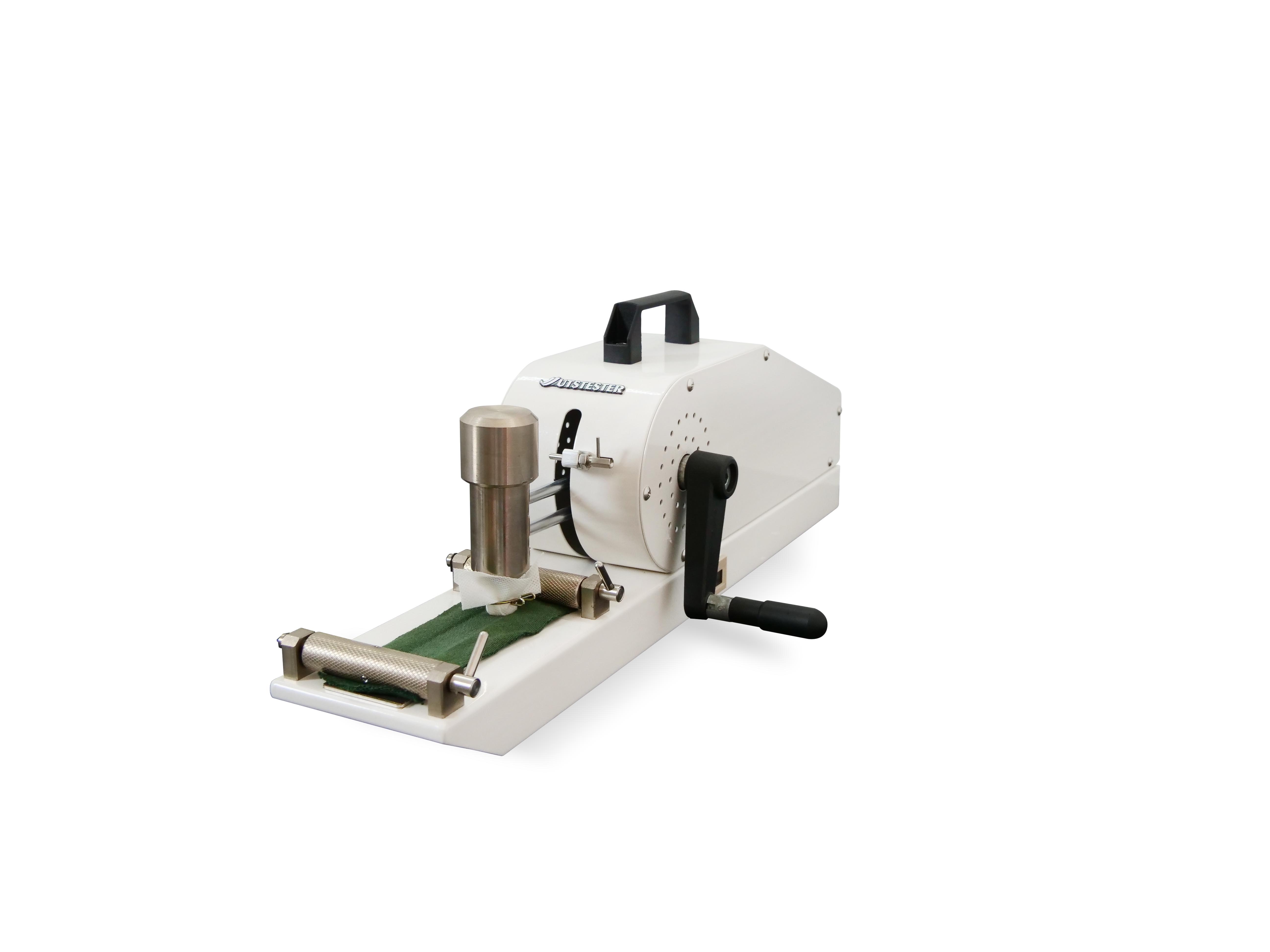
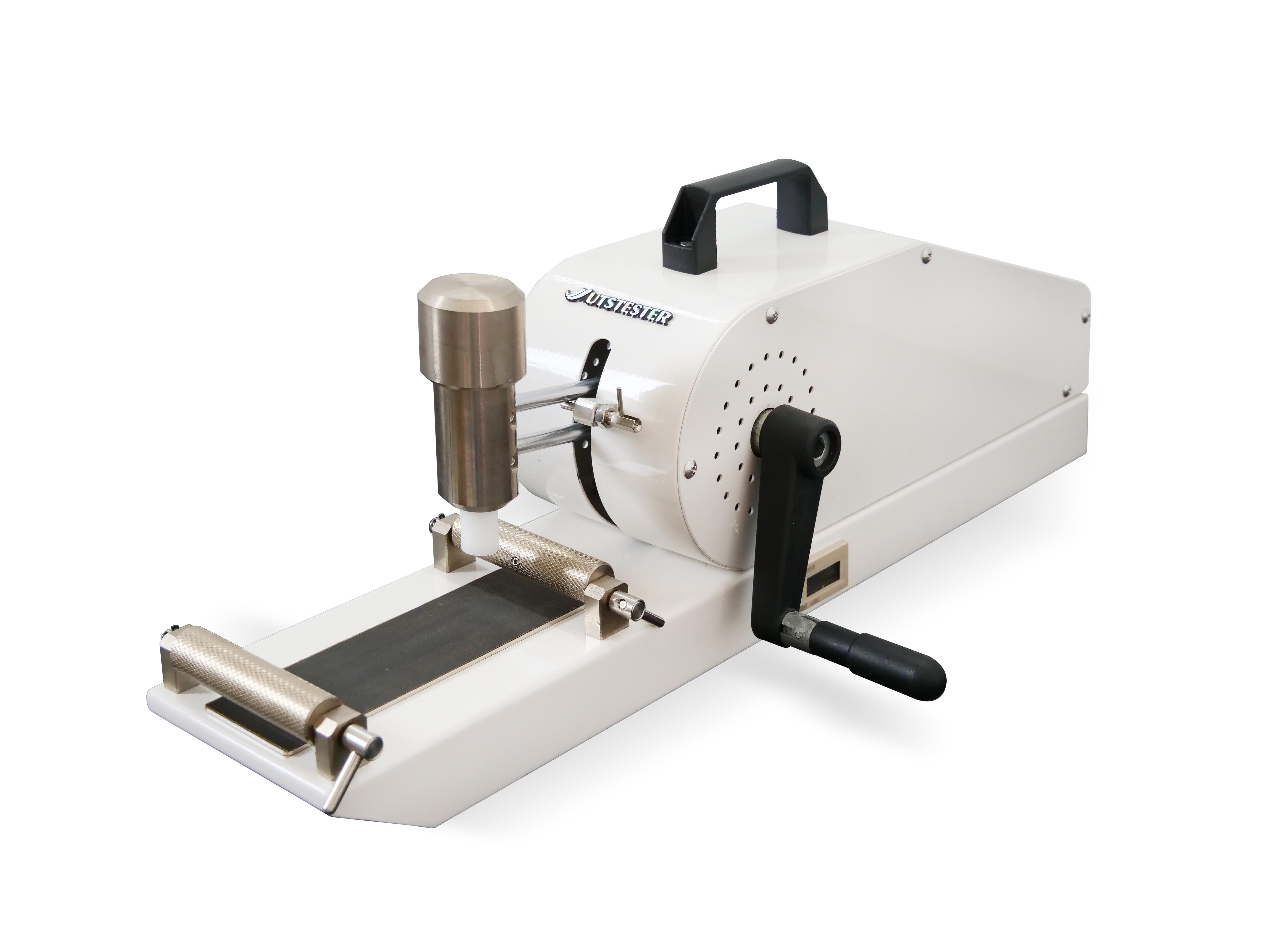
Test Overview: A pretreated standard specimen is clamped horizontally. A test flame of specified height (e.g., 20mm) is applied to the free end for a defined duration (e.g., 30 seconds) or until reaching a predetermined mark before removal. The sample's flaming burn time, burn length, and burn rate are then precisely recorded. Based on standard criteria, this fundamental flame-retardant test method evaluates the relative ease of horizontal combustion for materials. It primarily simulates ignition scenarios for horizontally laid materials like carpets, floor coverings, and tablecloths.
During testing, the distance between the ignition source and the specimen's edge must be precisely controlled to ensure stable flame exposure. The time required for flame spread over a specific distance is recorded to calculate the burning rate.
2. Vertical Flame Retardancy Test: Simulates the burning behavior of vertically suspended materials
Test Principle: Evaluates a material's self-extinguishing capability, burning duration, and potential for burning droplets after controlled ignition in a vertical orientation. The critical test requirement is that the material must self-extinguish rapidly after the ignition source is removed. Any dripping burning particles must not ignite flammable materials below (e.g., cotton wool). This directly relates to preventing vertical fire spread and secondary ignition during a fire.
Test Overview: The vertical burning test involves vertically clamping a standard specimen subjected to two pretreatments (70°C, 7-day high-temperature aging and 23°C, 50% RH humidity conditioning). A flame is applied twice at the specimen's lower end for standard durations (10 seconds each, with intervals until self-extinguishment). Precise measurements are taken of the flaming burn time, smoldering burn time, and ignition of cotton wool by burning droplets after each flame application. A professional evaluation method determines the V-0/V-1/V-2 flame retardancy rating based on observations of the worst-performing pretreated sample.
During testing, the specimen must be placed in a sealed combustion chamber meeting the dimensional requirements of ≥330mm × 330mm × 765mm. The chamber interior must feature black walls to eliminate reflective interference, and a layer of cotton wool must be placed at the bottom to detect ignition risks from burning drips.
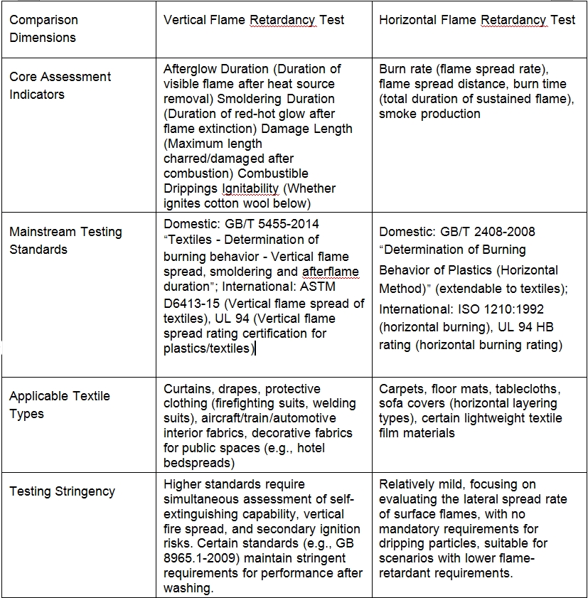
III. Key Dimension Comparison: Metrics, Standards, and Scope of Application
Based on differences in simulated scenarios, the core evaluation metrics, applicable standards, and application domains of the two tests are clearly differentiated. Specific comparisons are as follows:
IV. Practical Application: How to Select the Appropriate Test Method?
The two test methods are not a matter of “superiority or inferiority,” but rather “scenario suitability.” Enterprises must choose the test method based on the product's actual usage state and the regulatory requirements of the target market:
1. Situations Requiring Vertical Flame Retardancy Testing
Vertical flame retardancy testing is mandatory for products used in vertical hanging or vertical application scenarios, or when high safety ratings are required. Examples include:
1.1 Curtains and drapes for public spaces (must meet GB 50222-2001 B1/B2 requirements, tested per GB/T 5455);
1.2 Flame-retardant protective clothing (e.g., welding suits, industrial flame-retardant garments; must meet GB 8965.1-2009 Class A/B/C requirements, tested per GB/T 5455);
1.3 Aircraft and train interior fabrics (must prevent burning droplets from igniting degreased cotton, tested per GB/T 5455).
2. Situations Where Horizontal Flame Retardancy Testing is Preferred
Horizontal flame retardancy testing may be used when products are intended for horizontal application and basic flame retardancy requirements apply. Examples include:
2.1 Home carpets and tablecloths (no mandatory high flame retardancy rating required; focus on controlling burning rate);
2.2 Lightweight textile film materials (e.g., packaging films requiring assessment of surface flame spread risk);
2.3 Horizontal covering materials in automotive interiors (some standards permit horizontal testing for flame spread rate, e.g., FZ/T 01028).
V. Conclusion: Precise Testing Ensures Safety and Compliance
The core distinction between vertical and horizontal flame retardancy testing lies in “simulation scenario specificity”: Vertical testing focuses on vertical spread and secondary ignition risks, suited for vertically used products with high safety requirements; Horizontal testing emphasizes lateral spread rate, catering to products with basic flame-retardant requirements for horizontal applications. For textile enterprises, clearly distinguishing these differences not only ensures product compliance with target market regulations (e.g., GB 17591-2006 “Flame-Retardant Fabrics,” UL 94) but also enables optimization of material formulations and production processes through precise testing, thereby enhancing product safety competitiveness.
Email: hello@utstesters.com
Direct: + 86 152 6060 5085
Tel: +86-596-7686689
Web: www.utstesters.com